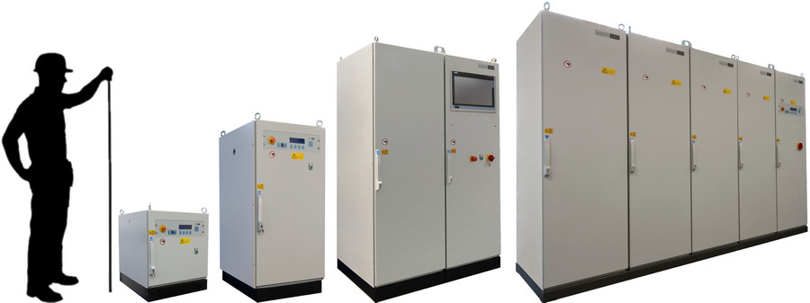
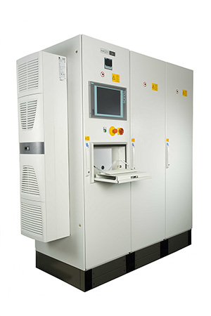
MAGSYS magnetizers allow the magnetization, adjustment and also the demagnetization of isotropic and anisotropic magnetic materials of different sizes. In particular, all highly coercive magnetic materials, such as Sm2Co17 or plastic-bonded NdFeB magnets, can be magnetized easily and with short cycle times. In addition to raw magnets, e.g. directly after production, complete workpieces with magnets already installed can also be magnetized.
The necessary energy of the magnetizer is mainly determined by the required magnetizing field strength and the size of the workpiece. The modular design allows best adaptation to your requirements. This results in an optimal price/performance ratio. At the same time, subsequent adaptation to modified magnet products is also possible.
The systems are suitable for 3-shift operation in an automated production environment as well as for use at manual workstations or in the laboratory. The systems can be used without problems in polluted environments, as they are often found in magnet production, as well as in clean rooms.
Standard built-in interfaces allow the connection to complex process controls and also the connection to automatic process control or quality assurance systems. Standard built-in pulse current measurement ensures the required magnetizing field strength for each magnetization.
The energy of the device is usually between 100 Ws and 300 kWs at a charging voltage of 850 to 5000 V. The figure shows different devices with different energy.

If required, electronic switching between several capacitance and thus energy levels is possible. This can be particularly useful in combination with several high-current outputs for connecting different magnetizing devices. Different pulse shapes - also electronically switchable combined in one device - can be realized.
The peak current of the system is measured so that it monitors itself.
When connecting a MAGSYS magnetizing device, its temperature is measured and switched off when the limit temperature is reached.
When connecting to the mains, we follow your specifications.
Application Examples
- Demagnetization directly after moulding for a better efficiency of sinter ovens
- Magnetization of raw magnets
- Radial magnetization of magnet rings with high precision
- Magnetization of mounted sensors to simplify the handling
- Magnetization of completely-assembled loudspeaker systems to avoid impurities during magnetization
- Magnetization and automatic calibration of complete fuse breaker systems
- Multipolar magnetization of moving coil systems for hard disk drives in clean rooms directly before mounting
- Multipolar skewed magnetization of rotors or stators in permanent excited electric motors
Special Features
- Fully digitally controlled
- Modular set-up
- Measurement and control of pulse current
- Control panel protected against moisture and dirt
- LCD resistant against magnetic field
- Simple operation
- Clearly arranged backlit graphical display
- Standard potential free serial interface
- Standard potential free inputs and outputs to connect the magnetizer to your PLC or other signal devices
- Standard temperature measurement of the connected magnetizing fixture
- Self test during start-up
- Extensive safety features
- Software updates via PC interface
- Optional: switchable energy adjustment
- Optional: auto or manual pulse selection (exponential, sine or demag)
- Optional: multiple outputs for alternating operation of several magnetizing fixtures
Technical Data
| Energy | Typically in the range of 100 Ws to 300 kWs; optional: the energy can be adapted by switching the capacitors. | |
| Capacitor bank | Bipolar metal paper capacitors. The capacitors contain PCB-free oil. | |
| Display | Graphical LCD 125 mm x 35 mm², backlit, contrast adjustable via menu. | |
| Keyboard | Environmentally protected against moisture and dirt. | |
| Max. voltage | 5000 V; the voltage and the generated magnetizing field strength can be preset manually via the control board or via the serial interface | |
| Voltage measurement | The voltage at the capacitor banks is adjusted within the range of 200 to 5000 V with an accuracy of ± 1%. | |
| Pulse shapes | ||
 |
Sine- shaped pulse |
Sine-shaped rise of the magnetic field with sine-shaped decay. This type minimizes the fixture's heating up. |
 |
Exponential- shaped pulse |
Sine-shaped rise of the magnetic field with e-shaped decay. This type causes the least possible rate of change of the magnetic field and thus minimizes possible problems with eddy currents. |
 |
Demag pulse |
Sine-shaped rise of the magnetic field with e-shaped decaying amplitude. For magnetization or demagnetization of the workpieces. |
 |
(Optional) Switchable pulse shape. |
|
| Outputs | The magnetizer has one standard high-current output. As an option, additional outputs are possible. | |
| High-current connection | Connection of the magnetizing fixture via massive brass bolts in a robust connection box on the back side of the device. As an option, the connection can also be on the front side or via plug and socket connectors. | |
| Output current | max. 50 kA during normal operation. The real output current and the pulse duration depend on the impedance of the magnetizing fixture. | |
| Current measurement | The magnetizing current is measured and displayed. There is a potentiol free analog output to control the pulse shape. | |
| Output impedance | Typically 2.5 µH / 2 mOhm | |
| Load impedance | The permissable impedance of the magnetizing fixture should be higher than 8 µH / 10 mOhm. | |
| Pulse rise | The pulse rate (di/dt) is max. 1000 A / µs. | |
| Charging unit | The load to the mains supply is kept nearly constant during the charging process. This gives a minimum charging time with minimum power loss. The control is synchronized with the line frequency. This avoids excessive load current and disturbing spikes on the mains supply. | |
| Charging power | Depending on the required cycle time, you can choose between different charging types: 600 Watts, 1800 Watts and 3600 Watts. Other charging powers on request. |
|
| Charging time | The charging time depends on the total energy of the magnetizer and the charging power of the charging unit. It is determined as charging time = energy / charging power; typical times are between 1 and 30 seconds. | |
| Cycle time | The typical cycle time is charging time + 500 ms. | |
Control and Operation
The machine is internally controlled by a Motorola microprocessor. The operation panel is equipped with a foil keyboard, thus being protected against moisture and dirt. The information is displayed on a graphical LCD (visible area 135mm x 40mm). The display is resistant against magnetic fields and is fitted with green background illumination.
By using the keyboard, you can input values such as charging voltage, limits of peak current monitoring, selection of output, and other parameters. Manual control of recharging, firing etc. also makes use of this keyboard. On the other hand, it is also possible to use a remote control and the device´s automatic control system. All relevant parameters are stored permanently inside the magnetizer, so that in case of power fail or after switching off the machine none of these data are lost. When switched on again, the magnetizer can continue operation without any need of new entries.
The voltage of the capacitors is permanently displayed. After a pulse has been fired, the peak current is also displayed.
Moreover, the software contains several service functions to ease check of the machine in case of an accident.
The magnetizer's serial interface allows fast software updates. The only thing required is a PC. By this, any changes in order to fit the equipment to varied production environment can be done within short time and at low cost.
Safety Features
The magnetizer is equipped with a number of safety features. Through these, a trouble-free and safe operation of the magnetizer can be ensured.
| Charging process | The charging process is continuously controlled by the microprocessor system. During malfunction the power unit is separated from the line supply and will be discharged. |
| Temperature | The temperature of the magnetizing fixture is measured and displayed. On reaching the selected limit values, you will hear an alarm and the magnetizing system will be stopped. |
| Capacitor voltage | The voltage at the capacitor banks is controlled both by the microprocessor system and by an independent circuit. |
| Emergency off | The magnetizer is equipped with an emergency off button on the front side. |
| Discharge of capacitor banks | The capacitor banks are automatically discharged during malfunctioning of the system or during power failure. This can be done manually via the operating panel. |
| Fixture control | To recognize errors in the magnetizing fixture early, the ohmic resistance of the fixture is permanently controlled. If no fixture is connected or if the resistance exceeds 3 W, any further magnetization will be stopped and an error message will be issued. |
| Current monitor | The output current is measured and displayed during magnetization. The minimum and maximum limit values can be selected via the control board. The system will be switched off when these limit values are exceeded. |
Interfaces
Digital Outputs (to customer's PLC)
| Number | 8 |
| Voltage | DC 24 V; external source |
| Current | max. 500 mA; short-circuit proof |
| Technique | P switching or M/P switching |
| Standard | IEC1131 (24 V DC) |
Digital Inputs (to customer's PLC)
| Number | 8 |
| Voltage | 5 - 34 V |
| Input | typ. 2.2 kOhm |
| Standard | IEC1131 (24 V DC) |
Serial Interfaces
| Standard | EIA 232 |
| Connector | 9-pole plug DE-9 |
| Baud Rate | max. 9600 Baud |
Standard Accessories
- Operating manual (German or English)
- Complete schematics
- List of recommended spare parts
- Set-up manual
- Troubleshooting
- Parts lists
- CE-Declaration
Options
| Manual selection of pulse shape (e-shape, sine-shape or demag pulse) |
Manual or electronic selection of capacity |
| Electronic selection of pulse shape (e-shape, sine-shape or demag pulse) |
Processing of external measuring signals to control the calibration or quality control (Hall probes, fluxmeters etc.) |
| Additional high-current outputs | External control and signal elements (e.g. hand or foot pedal switch) |
| Connection to the magnetizing fixture via high-current plugs | Realization of simple additional control sequences |
| Special enclosures (higher degree of IP protection) | Adaptation of line voltage |
Basic Data
| Dimensions | depending on type |
| Weight | depending on type |
| Protection | IP 20 according to DIN 40050 (touch protection; protection against medium-sized objects diameter >12 mm; no water-protection); Option: higher protection degree. |
| Color | RAL7035 light gray, RAL7030 stone gray, other colors on request |
Power Supply
| 600 W Charging Unit | 230 V AC ± 10% ; 16 A; 1 Phase; 50 Hz ± 5%; approx. 2.5 kVA 110 V AC ± 10% ; 32 A; 1 Phase; 60 Hz ± 5%; approx. 2.5 kVA |
| 1.8 kW Charging Unit | 400 V AC ± 10% ; 16 A; 3 Phases; 50 Hz ± 5%; approx. 7.5 kVA 200 V AC ± 10% ; 16 A; 3 Phases; 60 Hz ± 5%; approx. 7.5 kVA |
| 3.6 kW Charging Unit | 400 V AC ± 10% ; 32 A; 3 Phases; 50 Hz ± 5%; approx. 15 kVA 480 V AC ± 10% ; 28 A; 3 Phases; 60 Hz ± 5%; approx. 15 kVA |
Other line voltages can be realized without any problems.


